

Gather ’round to hear a tale of how AI pair programming with Claude Code helped to crack a CAD file format neither of us understood, turning a five-day investment into a saved $24,000 per developer per year. A tale worthy of Grimm!
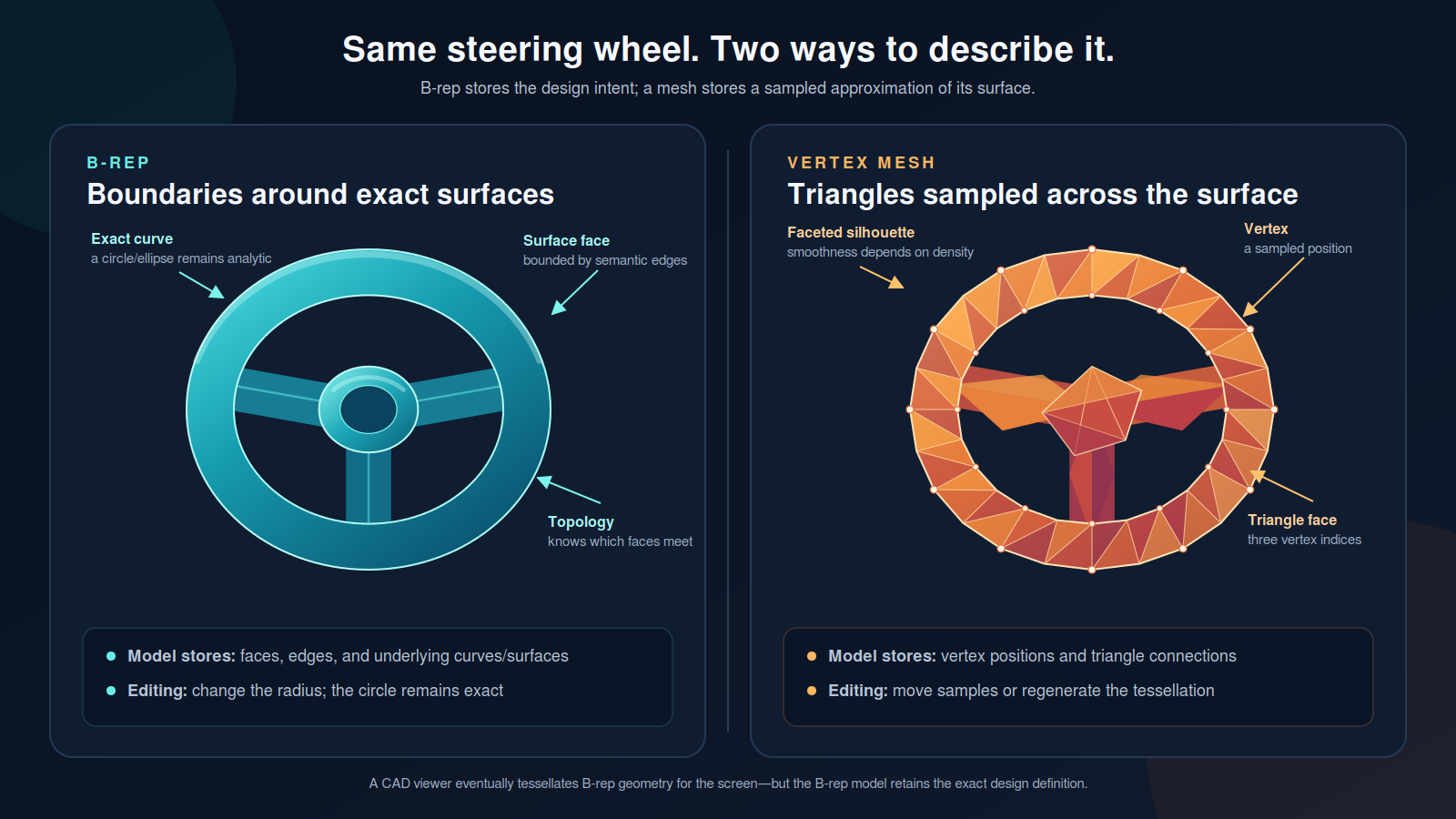
Once upon a time there was a dashing software engineer, lush of beard and smelling lightly of sandalwood. A client had given him a task to convert CAD data for an aircraft engine into something that a Virtual Reality application written in Unity could understand as a model. This was difficult, because CAD data describes surfaces (“boundary representation”, or B-rep), but Unity only understands meshes (groups of interconnected polygons).
Our hero searched valiantly for a weapon, but could only find items that were suspiciously crafted or extremely expensive. “$24,000 per year per developer?!” he cried. “That’s absurd!” But so it was, and he prepared an email to his client, ready to request such a drastic expense.
Suddenly an Idea came to him. “This file format,” he pondered, “is an Open Specification. It has its own ISO standard! Surely I can get a copy of the standard and implement what I need.” For he had found that the CAD files did indeed have meshes in addition to B-rep data. But how to extract them?
He went off in search of the mage, Claude, to see if their combined effort could crack the files open and deliver their bounty.
The difficulty of CAD files
I’ll stop with the narrative voice.
The client had sent us CAD data, comprising about 9,000 different .jt files (Jupiter Tessellation). When the client’s CAD program had exported the models, it created three different tessellations from the B-rep data and encoded them into the files, so each file contained B-rep, LOD0, LOD1, and LOD2, where LOD is a “Level of Detail” or a tessellation with a specific target polygon count. The tessellations were, more or less, representative of meshes; thus my desire to scan the files and extract what we needed.
I didn’t get far.
I want to be clear about how difficult this format is to decode, even with the specification printed out and on my desk, so I’m going to abandon the notion “write so people can understand” and just dump some words:
A Shape-LOD payload is not a serialized mesh, but a prediction-coded, recursively compressed description of the operations necessary to reconstruct one. Its Topologically Compressed Vertex Records distribute connectivity symbols across context-selected Int32CDP streams, including eight independent face-degree contexts, whose codec trees may combine Bitlength, Arithmetic, Chopper, Move-to-Front, and uncompressed leaf representations. Once the packet trees have been decoded, field-level predictors reversed, and the post-prediction symbol arrays validated by their composite hash, those arrays parameterize a state machine (see “Annex D”) that incrementally constructs the dual representation of the intended primal vertex-face topology. Only after dual-to-primal inversion, polygon triangulation, coordinate dequantization, and corner-attribute seam expansion does the payload resemble the indexed vertex mesh that an ordinary graphics API expects.
Yeah, I know. Why I couldn’t tackle this on my own, I’ll never know.
I turned to Claude and threw the spec into the context with my normal development prompts, while whimpering and pleading for help. Claude and I churned for two days and failed. I was stuck wrapping my head around what a “codec tree” was, and Claude was having a hard time with how the codec trees’ encodings can be recursive. Claude would look at the output of our decoding, declare “the hashes don’t match”, and try again. I would scour the specification and look for where these hashes were defined. At some point Claude gave up, then I gave up, and I went back to evaluating commercial CAD libraries and utilities.
It didn’t take too long before I ruled out my last, most expensive commercial option. It worked, kind of, most of the time, but the resulting meshes seemed to have undergone a kind of hedgehogification. Demoralized, I reflected on the self-written library and decided it was worth another shot, but with better guardrails.
Five rules for AI pair programming
I had used my default Claude Code customizations for the initial attempt, but in hindsight they weren’t nearly meticulous enough. I needed something tighter, something that would constrain the agentic sessions to a more narrow path. Ideally a path toward victory, but at this point I wasn’t too picky.
So I came up with some rules:
- Start with a trivially simple case. I found an open-source JT project with example JT files, and conspicuously chose the ‘3D Cube’. If we can extract LOD data as a mesh, it should be trivial to validate that we have, in fact, extracted a cube1.
- Log all hypotheses before implementation. We had a running
HYPOTHESES.mdfile that logged everything we had tried or were currently trying, and each session would use that file to ensure that we weren’t attempting something that had previously failed. This rule also short-circuited a few cases where, due to the recursive encoding scheme, the agents were looping fruitlessly. - If we can’t measure it, build a measurement device. “How often does the thing we’re trying to do actually happen? Do we need to worry about it?” were questions that came up more frequently than I would have guessed. Whenever that happened, we didn’t speculate; we built a small command-line utility that would get us the data we needed to make a good decision. We collected about a dozen such utilities over the implementation effort.
- Leave a trail of regression tests behind successes. Did we just decode a value correctly? Log it, add a test. This ensured we didn’t break anything important when testing a new hypothesis.
- Lean on me and my human eyeballs. We were, after all, decoding 3D objects, so it only makes sense for the 3D Entity, me, to give a pass/fail grade to the decoded results. This rule especially came in handy when the meshes were being extracted correctly but the validation checksums were not being calculated correctly. My human eyeballs were able to immediately determine that the meshes weren’t the problem, it was the checksum implementation.
Hypotheses logging in AI pair programming
The hypothesis logging and utility building were especially valuable. The spec tended to organize details horizontally. Segments, nodes, data types, and algorithms were all in different sections or appendices. A description of a full vertical implementation path simply didn’t exist in the document. Thus it was sometimes necessary to throw spaghetti at the wall and see what things stuck. For example, the topological data ended with a hashed value that an implementer could use to validate that they had extracted the data correctly2, but the hashing algorithm was presented in a different section than the topological data, and there was never a clear “here is how you apply this algorithm to the data”. Here’s a snippet from our HYPOTHESES.md file that helped guide our pasta-flinging:
| Hypothesis | Result |
|---|---|
| The composite hash probably covers raw CDP output. | No. that passed only 37% of the corpus. |
| Perhaps Lag1 should be applied from element 1 before hashing. | No. that fixed some segments but broke previous successes. |
| The Lag1 fields may use four literal primers, with accumulation beginning at element 4, and the hash may cover the accumulated values. | Yes. applying that rule to both vertex_flags and split_face_syms produced 16,596/16,596 passing segments. |
The hypotheses were falsifiable, and we used a combination of code modification (i.e. the hashing algorithm and when to apply it) and a custom-built measurement device to work through our list until we found a hypothesis that stuck to the wall.
One of the first tools we built after a potential successful mesh extraction was an OBJ exporter, which just wrote the 3D object out in the OBJ file format, which is natively viewable on macOS. The first time I clicked on the file and saw, not a mess of static, but an actual cube? Indescribable.
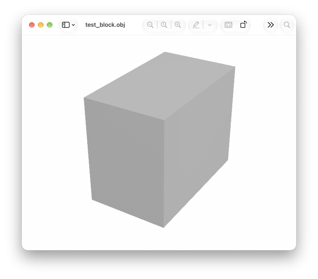
There was still a lot of work to be done after getting a cube, don’t get me wrong. Cubes, it turns out, are a little simpler than jet engines. But it was a bafflingly short road to walk once these rules were in place.
Follow-on benefits
In addition to getting to a working utility fairly quickly, the rules above resulted in code that was super easy to expand upon. Within short order we were able to:
- Create an integration for C# consumers
- Create a couple of desktop applications to aid in different extraction/analysis tasks
- Create a validation utility for further CAD file sets, to ensure they were exported correctly for our processing pipeline
- Compile the library to WebAssembly and make a web-based CAD viewer
That last one was super interesting. We went back and forth with the CAD people a few times and had dialogues like this:
CAD person: Okay, I’ve configured the export dialog according to your email and I have a set of files here. Will they work for you?
Me: Can you send them to me for testing?
CAD person: … no, they’re confidential and can’t be transmitted electronically
Me: Well… can I send you this application I wrote that validates CAD files?
CAD person: … no, our desktops are locked down by IT policies
Me: …. well, I guess let’s assume it works and I’ll physically come pick up the file on an encrypted drive, and if it doesn’t work I’ll email you and we can do this again in a few weeks.
Not ideal. But by compiling to WebAssembly, the CAD person could navigate to a website and point their browser at their own filesystem, with nothing leaving their machine, and still get all the benefits of our library’s validation.
Why AI pair programming worked the second time
The real lesson for me was that a fruitful pairing of human and agent needs to lean into the strengths of each. I, as a human person, have human eyeballs, but I also have experience in developing software and framing experiments. I can recognize circular thinking, and exercise sound technical judgment, or at least point out when something doesn’t make any sense. The agent, on the other hand, has far more breadth, speed, and tenacity. Like, so much tenacity.
This is not something I could have taken on myself; I simply don’t have the experience with CAD files. Claude didn’t either, it turns out. But together, leaning on each others’ strengths, we were able to make real headway, fast. The entire (second) effort, which for the record took FIVE CALENDAR DAYS, was framed from this position of individual strengths. And the result of those FIVE CALENDAR DAYS saved our client $24,000 per developer per year and resulted in a utility that can process all 9,000 CAD files for a single engine in less than 20 minutes.
So maybe the real lesson is to start working for the CAD people; that seems to be where the money is.
- I use the word ‘cube’ throughout, but the edges are not equal length. I wanted to make sure that we were correctly extracting the correct length, width, and height values, and if they were all the same I wouldn’t have been able to tell. ↩︎
- This description is broadly correct but not the full picture. The full picture, of course, is over a thousand words, and I’d prefer not make anyone’s eyes glaze over. ↩︎
✨ AI Post Recap
An SEP lead engineer and Claude Code failed for two days to decode the compressed mesh data inside JT CAD files, then got a working decoder in five days after adding rules to the agentic sessions. The rules were to start with a trivial test case, log every hypothesis in a shared file, build a measurement tool instead of guessing, add a regression test after each success, and let the human judge visual output. The resulting library processes 9,000 CAD files in under 20 minutes and replaced a commercial tool priced at $24,000 per developer per year.
What rules make AI pair programming work on a hard problem? Start with a trivially simple case, log every hypothesis before implementing it so the agent never retries a failed idea, build a small measurement utility whenever a question comes up, add a regression test after each success, and have the human judge results the agent cannot see, like whether a mesh looks right.
Can you convert JT CAD files to meshes without buying commercial software? Yes. JT is an open ISO standard (ISO 14306), and exported JT files often already contain tessellated level-of-detail meshes alongside the B-rep surfaces. Decoding the compressed mesh payload is the hard part, but it is doable with the specification and disciplined experimentation.
How do you stop an AI coding agent from looping on failed ideas? Keep a hypotheses log that the agent reads at the start of every session, write each hypothesis so it can be proven false, and test it against the full data set with a purpose-built measurement tool rather than letting the agent speculate.
